
Battery Cable Size Chart: AWG Guide for 12V, 24V, 48V & 51.2V Systems
Battery Cable Size Chart: AWG Guide for 12V, 24V, 48V & 51.2V Systems
Undersized battery cable is one of the most common failure points in commercial energy storage installs. It runs hot, it wastes energy as voltage drop, and in a 48V or 51.2V LiFePO4 cabinet it can soften insulation, trip BMS protection and, in a worst case, start a fire. This article is the battery cable size chart you want on the bench before you crimp anything: a voltage-drop-based AWG guide for 12V, 24V, 48V and 51.2V systems, written for solar installers, EPC contractors and electricians who wire LiFePO4 banks in commercial and industrial projects.
The tables below cover continuous current from 10A to 300A and round-trip runs from 5 ft to 50 ft, with the recommended AWG for a maximum 3% voltage drop. Every value is calculated from copper conductor resistance and standard 75°C ampacity, so you can size a battery-to-inverter run, a battery interconnect or a busbar feed without guessing. If you remember one thing, remember this: current sets the minimum cable thickness for safety, and length sets the minimum thickness for efficiency. Most wiring faults come from ignoring the second half.
How to Read a Battery Cable Size Chart
A battery cable size chart answers one question: what gauge carries this current over this distance without excessive loss. Three inputs drive the answer, and every chart in this article uses the same three:
- Current in amps. The continuous current the circuit actually carries — inverter input current at full load, plus any DC loads sharing the run.
- Round-trip cable length in feet. Both conductors — positive plus negative — including routing inside the cabinet. One-way length × 2.
- Acceptable voltage drop. Target ≤3% of system voltage, ideally ≤2% for sensitive loads.
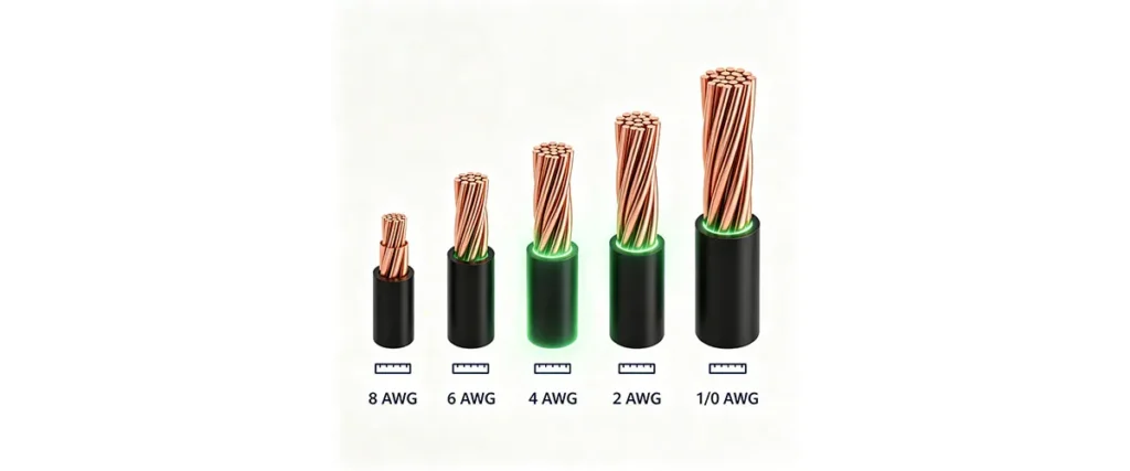
AWG (American Wire Gauge) numbers run inversely to thickness: 4 AWG is thicker than 8 AWG, and 1/0 is thicker still. Every three AWG sizes roughly doubles the cross-sectional area and halves the resistance. The metric alternative is mm², which states the cross-sectional area directly: 8 AWG ≈ 8.4 mm², 4 AWG ≈ 21.2 mm², 1/0 AWG ≈ 53.5 mm². European spec sheets and many 51.2V pack manuals quote mm², so keep both in mind.
When someone asks what gauge is battery cable, the practical answer is usually 10 AWG to 4/0 AWG depending on the system — and the exact battery cable gauge you need for a specific run is what the chart below shows.
The Full Battery Cable Size Chart (12V / 24V / 48V / 51.2V)
This battery cable sizes chart is the centerpiece of the article: recommended AWG for 10A to 300A over round-trip runs of 5 ft to 50 ft, sized for ≤3% voltage drop on 48V systems. It is a dc wire size chart built for battery circuits, not AC house wiring — and unlike a generic dc current wire size chart, it accounts for both ampacity and distance. Round-trip length means the total length of both conductors, not the distance from battery to inverter.
| Current (A) | 5 ft | 10 ft | 15 ft | 20 ft | 30 ft | 50 ft |
|---|---|---|---|---|---|---|
| 10A | 10 AWG | 10 AWG | 10 AWG | 10 AWG | 10 AWG | 10 AWG |
| 20A | 10 AWG | 10 AWG | 10 AWG | 10 AWG | 10 AWG | 10 AWG |
| 30A | 10 AWG | 10 AWG | 10 AWG | 10 AWG | 10 AWG | 8 AWG |
| 50A | 8 AWG | 8 AWG | 8 AWG | 8 AWG | 8 AWG | 6 AWG |
| 75A | 4 AWG | 4 AWG | 4 AWG | 4 AWG | 4 AWG | 4 AWG |
| 100A | 2 AWG | 2 AWG | 2 AWG | 2 AWG | 2 AWG | 2 AWG |